Switchgear Expansion RFQ: Spare Feeders and Space Checks
Many factory and park projects ask for “extra spare feeders” in a switchgear quotation, but that phrase is too vague for a purchase order. A spare breaker, an empty withdrawable unit, a blank cubicle, a reserved cable trench opening, and a future bay at the end of the lineup are different engineering and commercial items.
The short answer is: a switchgear expansion RFQ should define the future load scenario, feeder schedule, installed spares, physical spare space, busbar and fault-study basis, cable entry, control and metering space, room dimensions, ventilation assumptions, and document deliverables. Final suitability still depends on approved project drawings, protection coordination, short-circuit study, local code, utility requirements, AHJ review, supplier datasheets, routine verification or test records, and site commissioning by qualified personnel.
Use this article as a procurement checklist. It does not replace the electrical designer, EPC, utility reviewer, registered engineer, protection specialist, or local authority.
Start with the expansion case, not a percentage
It is common to request “20% spare feeders” or “space for future expansion.” Those numbers help during budgeting, but they do not say what must be manufactured. One future feeder may need a small outgoing breaker; another may need motor control, metering CTs, communication terminals, control power, cable termination space, and a larger compartment.
A switchgear lineup is a system of busbars, incomers, feeders, protective devices, control wiring, cable compartments, interlocks, ventilation paths, and access zones. Spare capacity should therefore be described as a future operating scenario, not only as a cabinet count.
An industrial buyer planning a second production line should tell the supplier whether the future load is a motor control center section, transformer feeder, capacitor bank, bus-tie arrangement, renewable-energy interface, or several small distribution feeders.
RFQ matrix for spare feeders and future bays
This matrix is not a design calculation. It helps buyers compare switchgear offers on the same assumptions before manufacturing is frozen.
| RFQ item | What to specify or request | Why it changes the supply |
|---|---|---|
| Future load scenario | State project phases, load type, operating mode, standby source, future transformer, generator, solar or storage interface, and whether the spare is for normal service or contingency. | Expansion affects bus arrangement, incomer duty, interlocks, protection, cable routing, heat, and room layout. |
| Installed spare feeders | List spare outgoing circuits fully equipped at delivery, including breaker or switch type, metering, CTs, terminal blocks, labels, and auxiliary contacts where required. | A fully equipped spare has a different cost, wiring scope, test scope, and maintenance requirement from a blank space. |
| Blank compartments or future cubicles | Define whether the quote includes empty compartments, blank doors, reserved bus connections, spare sections, end-extension panels, or only floor space for later cabinets. | A future cubicle may require bus extension details, mechanical joining provision, enclosure alignment, and safe isolation method. |
| Busbar and short-circuit basis | Provide the latest single-line diagram, transformer data, utility fault level if known, and the study basis for engineering review. | Spare feeders are useful only if busbar, short-circuit rating, protection, and upstream equipment remain suitable. |
| Cable entry and termination | Confirm bottom or top entry, cable trench or tray route, cable quantity and size where known, gland plate needs, bending space, access side, and future duct openings. | The cabinet may have electrical spare ways but no practical cable path if cable entry is not planned early. |
| Functional unit type | State fixed, plug-in, withdrawable, or mixed arrangement where preferred. For motor feeders, identify DOL, star-delta, soft starter, VFD, or control-by-others assumptions. | Interchangeability, drawer size, compartment form, heat, access, and later modifications depend on the unit type. |
| Protection, metering, and control | Request a point list for relays, meters, CTs, VTs, control voltage, trip circuits, communication, BMS/SCADA, spare terminals, and reserve I/O where applicable. | Future circuits can fail because the power path was reserved but the control and metering space was not. |
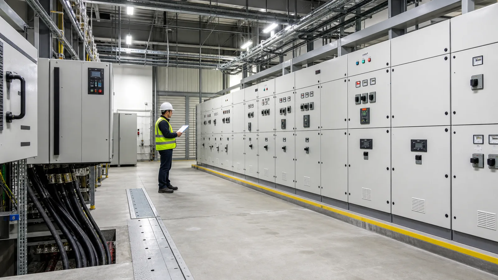
| Room and civil interface | Provide switchroom width, height, access side, door swing, cable trench, floor loading basis, lifting route, wall distance, future bay location, and ventilation concept. | A lineup that fits on paper may still block cable pulling, maintenance, heat removal, or later extension. |
| Documents and hold points | Request feeder schedule, single-line diagram, general arrangement, floor plan, cable entry drawing, schematic, terminal list, spare-space schedule, packing list, and verification or test records. | Documents keep the spare scope traceable through approval, factory inspection, delivery, installation, and future expansion. |
Spare feeders and spare space are not the same
An installed spare feeder is useful when the owner expects a known load soon after commissioning. It can be wired, labelled, tested, and kept ready according to the approved project scope. It also adds cost and may require maintenance even before it feeds a real load.
Reserved physical space is different. It may mean the room has space for another section, the existing bus can be extended, and the cable trench has future openings. That can be the right choice when the future load is uncertain, but it should not be described as “spare feeders” in the same line item.
Blank compartments sit between those two options. They may reserve cabinet space but still require future devices, wiring, protection settings, testing, and outage planning. Buyers should ask the supplier to identify exactly what is included now and what must be supplied or tested later.
Coordinate with transformer and fault-level assumptions
Switchgear expansion is often tied to transformer changes. A future larger transformer, second transformer, generator tie, or bus coupler can change available fault current and protection behavior. Before ordering additional feeder ways, compare the plan with the transformer short-circuit current and switchgear rating checklist.
Do not assume that adding spare feeders is safe just because the present load is small. The project engineer should confirm the final short-circuit study, protection coordination, earthing arrangement, cable capacity, temperature rise, and utility requirements. The supplier can quote equipment based on approved assumptions, but the system result belongs to the project design.
For medium-voltage lineups such as KYN28 switchgear, future bays may affect cable compartments, interlocks, protection relays, instrument transformers, earthing switch arrangement, and utility seal points. For low-voltage platforms such as MNS switchgear, spare drawer sizes, busway connection, heat, motor-control sections, and cable space need the same early review.
Cable space is usually the hidden constraint
Many expansion disputes are not about the breaker. They are about the cable path. A spare feeder may be shown on a single-line diagram, while the room lacks a spare trench opening, bending space, room for cable glands, rear access, removable plates, or a route through fire-stopped walls.
For overseas projects, this matters when the switchgear supplier, civil contractor, cable installer, and owner are in different procurement packages. Ask for a cable-entry drawing before production release, not only a front elevation. If the switchgear is part of a compact substation, confirm the enclosure, foundation, transformer, low-voltage board, and future feeder route as one interface package.
Standards help language, but do not choose the layout
Standards can help teams use the same vocabulary, but they do not create a universal switchgear layout. Where IEC practice is specified, IEC 61439-2:2020 is a relevant reference for low-voltage power switchgear and controlgear assemblies within its published scope. For medium-voltage metal-enclosed equipment, IEC 62271-200:2021 is a relevant IEC reference. In North American or ANSI-oriented work, NEMA’s switchgear resources are useful for standards terminology across utility, industrial, microgrid, and renewable applications.
These references are not interchangeable across markets. A project may use IEC, IEEE, ANSI, NEMA, GB/GB/T, utility rules, fire codes, seismic rules, owner standards, local AHJ conditions, or a combination. The RFQ should name the applicable market and project documents rather than asking for “international standard” switchgear.
RFQ wording buyers can adapt
“Please quote the switchgear lineup based on the attached single-line diagram, feeder schedule, switchroom layout, cable routing information, transformer datasheet, and project specification. Identify installed spare feeders separately from blank compartments, reserved bus provisions, and physical future-bay space.”
“For each spare or future feeder, state the included breaker or switch, compartment type, bus connection provision, CT/VT and metering scope, control wiring scope, terminal blocks, auxiliary contacts, labels, cable entry detail, and items excluded until future installation.”
“Confirm whether the future expansion assumption changes busbar rating, short-circuit rating, temperature-rise verification, enclosure size, ventilation, access clearance, floor loading, interlocks, protection coordination, utility review, or site testing.”
“Final acceptance remains subject to approved drawings, project short-circuit and protection studies, local code, utility requirements, AHJ review, supplier datasheet, routine verification or factory test records, and site commissioning by qualified personnel.”
Practical decision rule
Do not release a switchgear order because it says “spare feeders included.” Release it only when the quotation shows what is fully equipped now, what is merely reserved, what can be extended later, what assumptions control the ratings, and what documents will prove the scope.
A good expansion RFQ does not make the project over-complicated. It prevents the owner from discovering, during the next production phase, that the cabinet had spare labels but no real path for the future circuit.
