Transformer Cable Box RFQ: Terminal and Entry Checks
A transformer can meet the electrical rating on paper and still arrive with an interface that does not fit the site. Cable entry direction, terminal orientation, lug space, gland plates, grounding points, busduct flanges, CT location, and switchgear boundaries are often treated as installation details. In real projects, they can decide whether the unit connects cleanly or needs rework.
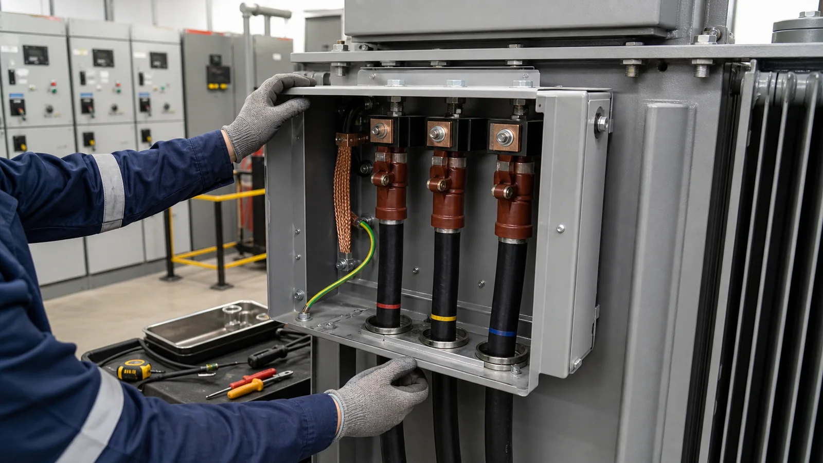
The short answer is: include the cable box and terminal interface in the RFQ before the quotation is compared. The buyer should state the cable route, cable type and quantity where known, entry direction, termination method, grounding and shield requirements, switchgear or busduct boundary, replacement constraints, and document evidence needed for approval. Final suitability must still be confirmed by project drawings, supplier datasheets, factory documents, local code, utility rules, AHJ requirements, and qualified electrical review.
This guide helps factories, EPC teams, commercial buildings, industrial parks, mines, renewable-energy sites, and utility projects prepare a clearer RFQ. It does not replace the project electrical designer, cable termination specialist, protection engineer, commissioning authority, or local inspector.
Cable interfaces belong in the purchase scope
Many early inquiries say only “11 kV/0.4 kV transformer, bottom cable entry” or “replace existing unit with same rating.” That may support budget screening, but it leaves too many assumptions open for a purchase order. Bottom entry, side entry, top entry, and busduct connection can each change floor openings, bend space, terminal orientation, enclosure size, and shop drawing coordination.
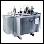
For an oil-immersed transformer, the interface may involve porcelain or plug-in bushings, cable boxes, tank earthing, oil containment clearances, radiator access, and lifting or removal routes. For a dry-type transformer, the interface may be shaped by enclosure airflow, terminal compartment access, bottom or top entry, temperature-control wiring, and room ventilation. A generic “standard terminal box” can mean different things across suppliers and markets.
Treat the transformer, cable, switchgear, and civil interface as one connection problem.
RFQ matrix for cable box and terminal interfaces
The matrix below is not a universal installation rule. It is a procurement checklist for finding missing information before drawings are frozen.
| RFQ item | Why it changes the order | What the buyer should state or request |
|---|---|---|
| Cable route and entry direction | Entry direction can change enclosure size, terminal orientation, foundation openings, lifting path, and maintenance access. | Provide the layout, trench or duct route, cable tray direction, floor opening, wall clearance, and preferred entry direction. Mark unknowns as drawing-review assumptions. |
| Cable type and quantity | Single-core, three-core, armored, shielded, parallel runs, or large LV cables need different bend radius, support, gland, and termination space. | State cable voltage class, construction, conductor material, size, number per phase, shield or armor treatment, and termination kit type where selected by the project. |
| Terminal arrangement | Terminal height, phase order, neutral position, lug angle, palm size, bushing type, and clearances affect field termination. | Request terminal arrangement drawings before manufacturing. Confirm phase marking, neutral terminal, grounding point, lug responsibility, and project-specified hardware. |
| Cable box or terminal compartment | Cable boxes may be weather-protected, ventilated, gasketed, removable, segregated, or indoor-only depending on the specification. | Define indoor or outdoor location, enclosure concept, access doors, removable covers, gland plates, drain or condensation concerns, and space heaters if required. |
| Busduct or busbar interface | Busduct requires mechanical alignment, support, phase spacing, enclosure coordination, and responsibility split. | Provide busduct drawings, flange details, phase sequence, short-circuit study basis, flexible connection requirement, and who supplies the mating adapter. |
| Earthing and cable shields | Tank or enclosure earthing, cable shield grounding, armor bonding, neutral treatment, and surge protection are project-specific. | Provide the grounding diagram, utility requirements, shield termination method, earth bar location, and responsibility for bonding conductors. Final grounding must follow project design and local rules. |
| CTs, metering, and protection boundary | CT location affects wiring, accuracy responsibility, utility review, and test access. | State whether CTs, PTs/VTs, meters, relays, test links, and terminal blocks are inside the transformer scope, switchgear scope, or by others. |
| Replacement constraints | Existing cables may be too short, too stiff, differently phased, or routed through openings that do not match a new outline. | Send site photos, existing nameplate, terminal photos, cable measurements, foundation drawing, switchgear data, and outage or re-termination limits. |
| Documents and hold points | Fit-up problems are easier to solve during drawing approval than after delivery. | Request outline drawing, cable box drawing, terminal marking, gland plate detail, busduct interface drawing if applicable, accessory schedule, packing list, and final test report. |
Replacement projects need measured interface data
Replacement projects are where cable-box assumptions cause the most pain. A new transformer with the same kVA, voltage ratio, frequency, vector group, and impedance may still require cable rework if terminal height, box depth, phase order, bushing position, or neutral terminal location differs from the old unit.
Before requesting the quotation, collect clear photos of each connection side, the nameplate, cable box, terminal labels, cable entry openings, grounding straps, LV bus or cable lugs, and nearby switchgear. Include tape-measure photos where safe and allowed. If the transformer is energized, do not open live compartments for documentation; use existing drawings and qualified site personnel.
For replacement or parallel additions, the cable interface should be reviewed together with the transformer vector group RFQ checklist. Phase displacement, neutral arrangement, grounding, protection, and terminal marking are connected issues. A physically convenient cable layout is not acceptable if the electrical relationship is wrong.
Oil-immersed and dry-type interfaces are not the same
Oil-filled and dry-type transformers can both use cable boxes or terminal compartments, but the surrounding risks differ.
Oil-immersed units may require attention to tank accessories, radiator clearance, oil sampling access, pressure or oil-level devices, surge arresters, containment, fire separation, and outdoor weather exposure. If the cable box is attached to a tank wall, confirm inspection access, drainage, cable support, sealing, and future removal. Fire, environmental, lifting, and oil-handling requirements must be confirmed by project documents and local authorities.
Dry-type units often concentrate the interface inside an enclosure or indoor room. Cable entry should not block ventilation openings or fan paths. Terminal access, dust control, moisture, heater wiring, temperature controller leads, and room airflow may be as important as conductor fit.
Where a compact substation combines transformer, MV switching, LV distribution, and enclosure, the cable question becomes a package interface. The RFQ should say which cables enter each compartment, how separation is maintained, which drawings control the foundation opening, and where customer terminals are located.
Standards help define terms, but project files decide
Standards and industry guides can help buyers ask the right questions, but they do not approve a specific cable box for every market. NEMA’s transformer resources include guidance for transformer purchasing specifications and practical application topics. IEEE C57.12.70 addresses standard terminal markings and connections for distribution and power transformers in IEEE-based specifications. IEC 60076-1 is a common general reference where IEC power-transformer requirements apply.
Those references should not be treated as interchangeable defaults. A project may also be governed by IEC, IEEE, ANSI, NEMA, GB/GB/T, utility rules, building code, fire code, cable standards, grid code, owner specifications, or local AHJ requirements. Cable sizing, short-circuit withstand, touch-voltage risk, grounding, protection settings, fire separation, and site testing must be confirmed by the applicable project documents and qualified reviewers.
RFQ wording buyers can adapt
“Please quote the transformer with cable box and terminal arrangement based on the attached single-line diagram, site layout, cable schedule, switchgear drawings, and project specification. If any cable data is missing, state the quotation assumption clearly.”
“Submit outline drawings, cable box drawings, terminal marking drawings, gland plate details, busduct interface drawings where applicable, earthing terminal locations, accessory schedule, and terminal list for approval before manufacturing.”
“Confirm whether CTs, PTs/VTs, meters, surge arresters, cable glands, lugs, termination kits, flexible connectors, busduct adapters, heaters, and control terminals are included in the transformer scope, switchgear scope, or by others.”
“Final installation suitability remains subject to approved drawings, supplier datasheet, factory test report, local code, utility requirements, AHJ review, cable termination practice, protection coordination, and commissioning tests.”
A practical release rule
Do not release a transformer order while the cable interface is described only as “standard cable box” or “suitable for bottom entry.” Before manufacturing is frozen, the buyer should be able to identify the cable route, entry direction, terminal arrangement, grounding interface, switchgear or busduct boundary, and drawing evidence in one approved document set.
That discipline makes quotations more comparable and gives the site team fewer surprises. Keep the approved interface drawings with the commissioning file so the final check happens before energization, not during a rushed fix on the installation floor.
