LV Switchgear Separation Forms: RFQ Checks for Buyers
A low-voltage switchgear RFQ that only asks for “MNS type,” “GCK type,” or “drawout cabinet” is not specific enough for many factories and utility buildings. It may leave the most practical question unanswered: which live parts, busbars, cable terminals, functional units, and auxiliary devices are separated from each other during normal operation, inspection, and maintenance?
The short answer is: buyers should define the applicable standard basis, required form of internal separation or equivalent compartment arrangement, fixed or withdrawable unit philosophy, access direction, busbar and cable compartment boundaries, neutral and PE bar arrangement, metering and protection-device locations, spare-unit plan, and document evidence before approving drawings. Final acceptance remains subject to the project specification, supplier datasheet, local code, utility rules, applicable market standards, and qualified electrical engineering review.
This guide is written for procurement teams, EPCs, plant engineers, commercial building teams, mining projects, parks, and renewable-energy facilities comparing low-voltage switchgear quotations. It does not replace a switchgear design, short-circuit study, arc-flash study, protection coordination, or AHJ approval.
Internal separation is a maintenance question, not just a form number
Forms of separation are often discussed as if the highest form is always the best technical answer. That is too simple. A higher separation requirement may improve access boundaries for some work, but it can also change cabinet width, depth, ventilation, cable termination space, copper layout, drawer arrangement, inspection windows, cost, and delivery drawings.
For a production plant, the real question is more concrete: if one feeder is isolated, what nearby parts remain live, what barriers exist, where can the maintenance team safely inspect or replace a unit, and what work still requires the whole lineup or section to be de-energized? For a commercial building, cable access and metering compartments may matter more than drawer interchangeability. For a process plant or mine, motor feeders, control wiring, auxiliary power, and spare drawers may drive the decision.
In IEC-style projects, buyers may see Form 1, Form 2, Form 3, Form 4, and suffix language in specifications for low-voltage assemblies. In North American projects, the procurement language may instead focus on switchgear versus switchboard classification, metal-enclosed construction, drawout power circuit breakers, rear access, barriers, and the applicable UL, ANSI, IEEE, or NEMA basis. Do not force one vocabulary into another market without project approval.
RFQ matrix for separation and access
Use this matrix before sending an inquiry or approving a general arrangement drawing. It is not a universal design rule.
| RFQ item | What the buyer should state or request | Why it changes the order |
|---|---|---|
| Standard and market basis | Name the project basis, such as IEC 61439 series, GB/GB/T, UL 1558, ANSI/IEEE, NEMA, utility specification, or local code where applicable. | “Form” language, verification documents, labeling, test evidence, and inspection expectations vary by market. |
| Separation requirement | State the required form of internal separation or equivalent barrier/compartment description. If the project does not specify it, ask the engineer to define it before quotation comparison. | Higher separation can change structure, copper routing, terminal access, ventilation, and cabinet size. |
| Functional unit type | Clarify fixed, plug-in, removable, withdrawable, or mixed units for incomers, feeders, motor circuits, capacitor feeders, and spares. | A MNS withdrawable lineup and a fixed distribution cabinet can look similar on a single-line diagram but behave differently during maintenance. |
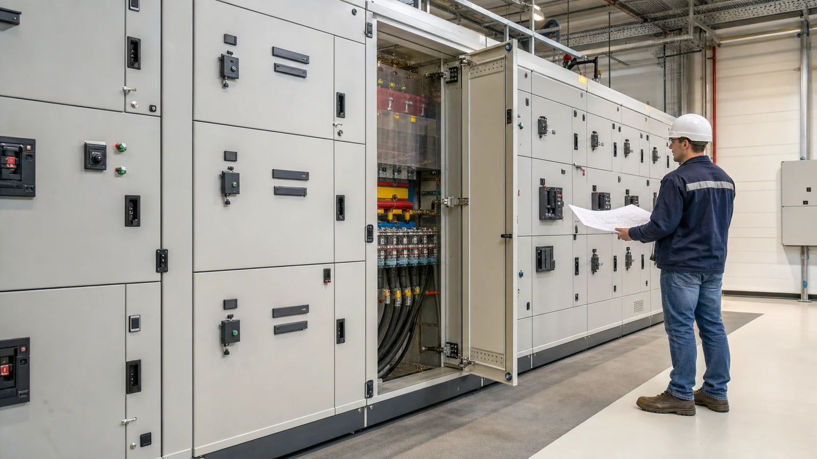
| Busbar compartment | Request drawings showing horizontal busbar, vertical busbar, barriers, joints, inspection access, and whether energized busbar exposure is possible during feeder work. | Busbar access affects safety planning, maintenance shutdowns, and thermal layout. Final work practice must follow site procedures. |
| Cable compartment | Define front or rear access, cable entry direction, terminal height, bending space, gland plates, CT location, shield or earth connection, and spare outgoing space. | Many site delays come from cable landing conflicts, not from the breaker rating itself. |
| Neutral and PE arrangement | Ask for neutral bar and protective earth bar routing, connection points, removable links if specified, and space for future feeders. | Neutral and PE details affect four-wire loads, metering, grounding, and commissioning checks. Final earthing design must follow project documents. |
| Metering, CTs, and relays | Identify which devices sit in the feeder unit, cable compartment, metering compartment, or separate control section. Use the protection CT and relay RFQ checklist when secondary wiring is unclear. | Device location changes wiring, access, sealing, test terminal blocks, and maintenance isolation. |
| Expansion and spare units | Define spare feeders, spare drawers, blank compartments, busbar extension, cable reserve, and future control-space allowance. | Separation and drawer sizing should support the expansion plan, not block it later. See the switchgear expansion RFQ guide. |
| Documents and evidence | Request single-line diagram, general arrangement, section views, compartment drawings, routine verification or test documents required by the project, wiring diagrams, terminal plans, and deviation list. | Quotations cannot be compared if one supplier includes only a concept layout while another prices verified compartments and drawings. |
Do not confuse separation with fault rating or arc-resistant design
Internal separation is not the same as short-circuit withstand rating. A separated cabinet still needs the correct rated voltage, current, busbar rating, short-time withstand current, peak withstand current, protective device duty, and installation conditions. Those values should be confirmed through the project short-circuit calculation, supplier datasheets, test evidence required by the specification, and local code or utility review. For transformer-fed boards, coordinate this with the transformer impedance and available fault current, not only with a catalogue label.
Internal separation is also not the same as arc-resistant switchgear or an arc-flash safety conclusion. Barriers can limit access to some parts during normal work, but they do not automatically provide a tested arc-resistant classification, define PPE, or determine incident energy. If the owner requires arc-resistant construction, arc-flash labels, remote racking, optical arc detection, or other safety measures, these should be written as separate requirements and reviewed with the site study.
Where separation affects transformer and capacitor projects
Separation details become more important when the LV switchgear is part of a package with a transformer, capacitor cabinet, or compact substation. A box-type substation may combine MV switching, transformer, LV distribution, compensation, metering, enclosure, ventilation, and earthing in one footprint. If the LV section uses fixed feeders but the owner expects drawer replacement, the misunderstanding may only appear after manufacturing drawings are released.
Power factor correction is another common interface. A capacitor feeder, detuning reactor, controller, CT signal, and ventilation path may need defined compartment boundaries. When the RFQ includes a GGJ or other compensation cabinet, coordinate the compartment and cable layout with the power factor correction cabinet RFQ guide rather than treating compensation as a small add-on.
For retrofit projects, do not rely only on the new single-line diagram. Collect photos, existing cabinet drawings, cable entry information, floor openings, rear access limits, spare cable lengths, metering seal requirements, and shutdown constraints. A technically sound separation requirement can still fail on site if cable bending space or access direction does not match the room.
Standards help, but the project decides
IEC 61439-1:2020 defines general rules for low-voltage switchgear and controlgear assemblies within its stated scope. IEC 61439-2:2020 covers power switchgear and controlgear assemblies and includes form-of-separation requirements within the IEC framework. For North American low-voltage power switchgear, UL 1558 and related ANSI/IEEE requirements may be relevant, while NEMA switchgear resources help buyers recognize market terminology.
Those references do not make one standard universal. The final requirement depends on the country, utility, owner specification, building code, electrical code, AHJ, service conditions, and the exact equipment type being ordered.
A practical release rule
Before releasing a low-voltage switchgear order, ask whether the approved drawings clearly show what is separated, what remains live during each normal operating state, how cables are landed, how CTs and control wiring are accessed, how future feeders are added, and which documents prove the quoted arrangement.
That rule does not make procurement responsible for switchgear safety design. It makes a hidden scope item visible early enough for the EPC, supplier, owner, and commissioning team to close it before the cabinet is built.
