Transformer Energization From a Generator: RFQ Checks
An emergency or standby generator can have enough nameplate capacity for the intended load and still struggle when a transformer is first energized. The missing question is often not “what kVA transformer?” but “which source closes onto which transformer, in what sequence, and what must the generator, switchgear, controls, and operating procedure do at that moment?”
The practical answer is to state the energization scenario in the RFQ and have the responsible power-system engineer review it before equipment is released. Transformer energization can produce a temporary magnetizing inrush that varies with the switching instant, residual flux, transformer design, source impedance, and system configuration. A generator, automatic transfer equipment, protection relays, and voltage-sensitive loads may each react differently. Final suitability must be confirmed by the approved single-line diagram, generator data, transformer datasheet, protection and control design, applicable project standard, utility requirements where relevant, local code, and commissioning procedure. This guide supports procurement clarification; it is not a generator-sizing method, protection study, switching instruction, or authorization to energize equipment.
Start with the operating sequence, not two kVA labels
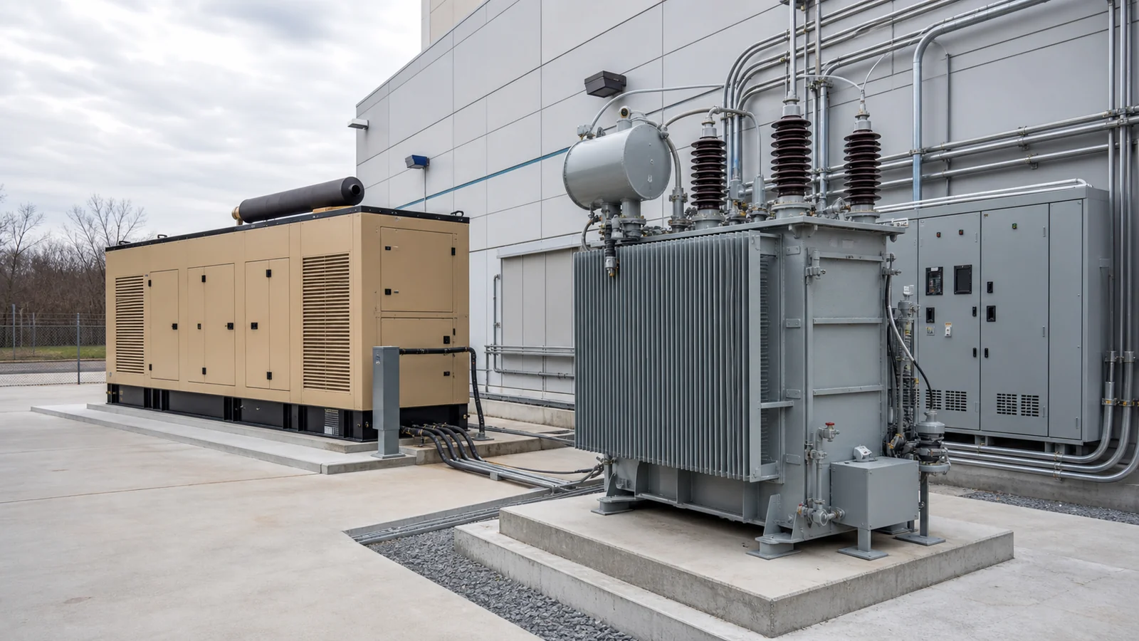
“Generator feeds transformer” can describe several very different arrangements. A generator may feed a transformer only during a utility outage, pick up a transformer that is already connected to an unloaded LV bus, restore a bus with motors and drives connected, or operate through an automatic transfer scheme. Some installations also have a bus tie, UPS, energy storage, or a second transformer that changes the source path.
Those cases should not be treated as interchangeable. A transformer connected to a stiff utility source may behave differently when supplied by a generator with its own voltage regulator, governor, transient response, and control limits. Likewise, a generator that starts a building successfully under one sequence may experience a different disturbance if a transformer is energized before load transfer.
Before comparison, identify the normal source, emergency source, switching devices, transformer primary and secondary bus, transfer mode, intended load state, and who owns the control logic. If the design is still preliminary, mark it as such rather than asking a supplier to assume a “typical” generator arrangement.
RFQ matrix: expose the generator–transformer interface
Use this matrix to find missing inputs. It does not prescribe a universal sequence or acceptance value.
| RFQ item | Why it matters | What should be supplied or confirmed |
|---|---|---|
| Operating modes | Utility service, generator service, maintenance bypass, testing, restoration, and parallel modes can place the transformer on different sources. | Provide the latest single-line diagram and a short narrative for normal, outage, test, and return-to-normal operation. |
| Energization sequence | Closing a generator breaker onto an unloaded transformer is not the same as transferring an already energized LV bus. | State which breaker or transfer device closes first, whether the transformer or LV load is energized at that point, and who approves the sequence. |
| Transformer data | Inrush response and protection behavior cannot be inferred from voltage ratio alone. | Provide rated data, vector group, impedance where specified, tap position or range, winding connection, accessories, and the final datasheet when available. |
| Generator and source data | Generator performance depends on the exact set, controls, and source path. | Provide the generator manufacturer’s rated and transient data, voltage-regulator information, source impedance assumptions, and any owner limits for voltage or frequency recovery. |
| Connected loads | Motors, drives, UPS rectifiers, capacitor banks, and process loads can change the event after the transformer is energized. | Describe which loads are connected, blocked, shed, or restarted during each mode. Harmonic and motor-starting questions may need separate studies. |
| Transfer and interlocks | Transfer equipment may permit, block, or time a switching action; bus ties can change source combinations. | Identify ATS, breakers, bus ties, mechanical/electrical interlocks, permissives, and the party responsible for functional logic. |
| Protection and metering | Inrush can be seen by protective devices, while generator-source faults and grounding can require different review from utility-source cases. | Provide relay list, CT/VT details, existing settings where relevant, grounding diagram, protection-study inputs, and the final test responsibility. |
| Test evidence | Factory documents alone do not prove the installed emergency sequence works. | Request drawings, control narratives, terminal lists, test scope, deviations, and named factory/site hold points. |
The transformer nameplate review guide helps collect the transformer information that needs to line up with generator and switchgear documents. For a replacement or an expansion beside existing equipment, also check the vector group RFQ guide; a matching kVA label does not establish a compatible phase and neutral interface.
Separate equipment scope from the system study
A transformer supplier can state the exact offered transformer configuration, terminals, accessories, drawings, and factory test records. A generator supplier can state the characteristics and controls of the proposed set. A switchgear supplier can state the supplied breakers, transfer equipment, relays, interlocks, and panel drawings. None of those individual scopes automatically proves the installed sequence is acceptable.
Ask the project team to identify the owner of the generator–transformer study and of the operating sequence. The review may need to consider source impedance, transformer magnetizing behavior, generator control response, anticipated load steps, motor restarts, relay performance, grounding, and the selected switching arrangement. The final assumptions and any calculated results should appear in controlled project documents, not be recreated from generic website values.
This distinction matters most when packages are bought separately. For a transformer feeding switchgear, the transformer data must be reconciled with the panel single-line, breaker duties, CT/VT allocation, relay settings, and interlock drawings. The short-circuit current and switchgear rating checklist explains why the project fault study, rather than a product family, is the basis for those ratings.
Questions that should pause an order release
Pause technical release when any of these answers is unknown:
- Does the generator ever energize the transformer directly, and is the downstream bus unloaded, partially loaded, or carrying automatic restart loads?
- Is the proposed sequence open-transition, closed-transition, intentionally isolated, or capable of parallel operation under the approved design?
- Which party validates generator voltage and frequency recovery, transformer inrush response, and relay behavior for the exact configuration?
- Are UPS systems, variable-speed drives, capacitor banks, large motors, or power-factor-correction stages blocked, staged, or already connected during transfer?
- Do transformer, generator, ATS, switchgear, and BMS/SCADA drawings use the same equipment tags, terminal boundaries, and operating mode names?
These are not reasons to reject a transformer or generator. They are prompts to close design assumptions before a factory builds equipment around the wrong sequence.
Test the intended sequence under project control
Factory tests can verify the ordered equipment within its scope. They normally cannot reproduce the complete site source, cables, load state, protection settings, and operating permissions. Site commissioning should therefore use a controlled procedure that distinguishes safe functional checks from live system tests and assigns the authority to approve each step.
Our pre-energization checklist covers the broader installed-system hold point. For generator-fed operation, add a clear record of the approved source path, starting and transfer sequence, initial load state, permitted alarms or trips, rollback action, communications requirement, and evidence expected after the test. Do not improvise switching logic during a live outage or use a supplier’s generic note as a site procedure.
Safe isolation and testing also depend on the applicable jurisdiction and project rules. In U.S. general-industry settings, OSHA’s control of hazardous energy rule addresses lockout/tagout programs and verification requirements; it is not a global commissioning standard. Other markets may use different legal, utility, owner, or authority requirements.
Standards provide context, not a universal design
IEC 60076-1 is a general power-transformer reference where an IEC basis is specified. It does not select a generator, determine transient performance, approve an ATS sequence, set relay values, or authorize site energization. IEEE, ANSI, NEMA, GB/GB/T, utility, owner, national, and local requirements may instead—or additionally—govern a project.
The applicable market and project specification decide the standard route. Any statement about generator capability, inrush, protection coordination, grounding, emissions, fire requirements, cable installation, testing, or commissioning remains subject to the approved engineering documents and qualified review.
RFQ wording buyers can adapt
State whether the transformer will be energized from the utility, a standby generator, or both. Provide the intended switching sequence, source path, connected-load condition, transfer equipment, interlock boundary, and responsible system-design party. Any unconfirmed information shall be identified as a quotation assumption.
Submit the transformer datasheet, vector group, tap basis, terminal drawings, accessory schedule, test-report scope, and deviations for the quoted configuration. The purchaser will provide available generator, switchgear, and control data for project review.
Generator–transformer compatibility, transient response, protection settings, grounding, automatic transfer logic, site testing, and energization authority remain subject to the approved project design, equipment-specific documents, applicable standards, local requirements, and qualified commissioning personnel.
A practical release rule
Do not release a standby-power transformer package until the buyer can point to one controlled document set that names the generator source, transformer, switching sequence, initial load condition, interlock boundary, study owner, and test owner. That is a useful procurement checkpoint: it makes quotations comparable without pretending that a transformer RFQ replaces power-system engineering.
