Transformer Foundation RFQ: Plinth, Rails and Anchor Checks
A transformer can be electrically correct and still become an installation problem when the civil interface is left until equipment arrives. A plinth that does not match the rail gauge, an anchor arrangement that conflicts with the base frame, a cable trench beneath the wrong side, or a crane route that cannot reach the final position can turn a routine delivery into a redesign.
Freeze the foundation only after the team has matched the supplier’s outline, mass, centre-of-gravity and mounting data with civil, cable and access drawings. The civil designer—not the buyer or a generic catalogue—must decide the foundation, reinforcement, anchorage, restraint where applicable, drainage, earthing and local safety measures. Final requirements remain subject to project documents, local code, utility requirements, AHJ review, supplier drawings and qualified engineering judgment.
This procurement checklist helps EPC, industrial and renewable projects prepare RFQs for oil-immersed transformers, dry-type transformers and compact substations. It is not an installation design.
Start with the equipment drawing, not a typical plinth
“Concrete base by others” is a scope note, not an interface definition. Before a foundation drawing is released, the project team should know which dimensions are preliminary and which will be supplied or confirmed after technical approval. This matters especially for replacement work, where an existing pad or rail set can tempt a buyer to assume a new unit will fit.
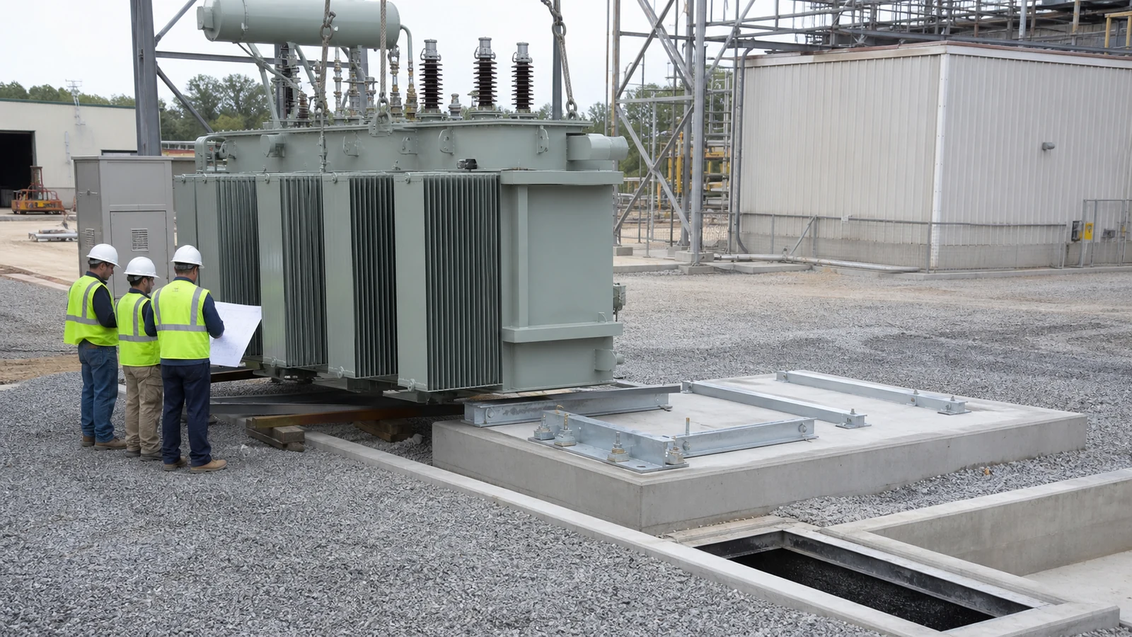
Ask for a dimensioned outline drawing that identifies the mounting plane, base-frame footprint, rail or wheel arrangement if supplied, anchor or hold-down locations if applicable, cable-entry side, bushing and radiator projections, control-cabinet door swing, lifting points, lifting clearances, shipping configuration, installed mass and centre-of-gravity information. If any value is still pending, mark it as a hold point rather than building the civil work around an estimate.
The drawing should also show what is outside transformer scope. Rails, anchors, trenches, containment works and final positioning may be project items; do not infer ownership from a general arrangement drawing.
RFQ matrix for foundation and mounting interfaces
Use this table to align teams. It does not prescribe values.
| RFQ item | What to state or request | Why it changes the installation |
|---|---|---|
| Installed location and arrangement | State indoor/outdoor location, proposed orientation, adjoining equipment, maintainable sides and applicable project layout drawing. | A transformer outline alone does not prove access around radiators, panels, terminals or cable boxes. |
| Final equipment data | Request outline, base footprint, installed and shipping mass, centre of gravity, mounting points, lifting points and approved accessory arrangement. | Civil loads, transport planning and lifting plans should use current supplier information, not a similar previous unit. |
| Foundation responsibility | Identify who designs the foundation, reinforcement, rails, anchors, grout, drainage and restraint; identify required approval documents. | A purchase order can otherwise leave the civil contractor and equipment supplier assuming the other party owns the interface. |
| Rail, wheel and anchor interface | State whether rails, wheels, base channels, stops, anti-roll or hold-down provisions are required, supplied or by others. Provide gauge, orientation and tolerance requirements only when confirmed by the final drawing. | Mounting details vary by product and project; an unverified rail gauge is a frequent late-stage fit risk. |
| Cable and earthing routes | Provide the single-line diagram, cable schedule, preferred entry side, trench or duct-bank location, earthing-conductor route and separation constraints. | Cable pulling space and earth connections can conflict with the base or with future access if shown too late. |
| Water, oil and fire boundary | State drainage, oil-containment, weather protection and fire-protection obligations that apply to the project, plus the responsible party. | These are site-system responsibilities; they cannot be established from transformer type alone. |
| Access and lifting plan | State delivery route constraints, door or gate sizes, turning limits, crane or forklift assumptions, laydown area and final set-down method. | A unit can fit its plinth but still be impossible to move into position safely. |
| Site conditions and restraint | Provide altitude, soil or floor information supplied by the civil team, vibration sources, flood exposure, wind/seismic design basis where applicable, and local code/utility requirements. | The installation design must address the actual site; the transformer supplier should not be asked to assume the civil design basis. |
Separate the four drawings that answer different questions
Teams often have one drawing labelled “layout” and expect it to resolve every interface. In practice, four linked documents usually make a cleaner handover:
- The electrical single-line diagram identifies transformer connections and adjacent equipment.
- The supplier outline drawing identifies supplied geometry, mounting and lifting information.
- The civil foundation drawing defines the project-designed base, anchors, drainage and restraint.
- The installation or lifting plan defines unloading, movement, setting and alignment.
Each document can change the others: a different cable-entry arrangement can move a trench, a transformer cable box can reduce pulling space, and a compact-substation enclosure can turn a plinth into a package-foundation issue. Use coordinated drawing review rather than asking one supplier to certify the whole site arrangement.
Check access as an operating requirement, not just a delivery route
A delivery route only answers whether the transformer can arrive. The project layout should also identify access for terminals, control cabinets, inspection, ventilation, cable termination, emergency egress and future replacement. Required clearances and safe working arrangements come from local rules and project design; do not copy them from another market or a product photograph.
For oil-immersed equipment, confirm access to radiators, valves, fitted accessories and control cabinets without crossing an unplanned drainage channel or removing permanent civil work. For dry-type equipment, confirm the room, ventilation, doors and cable route with the approved drawing. These checks complement the site-conditions RFQ guide; they do not replace ventilation, fire, earthing or structural reviews.
Replacement and expansion projects need measured data
For a greenfield site, civil drawings can follow the approved equipment. Replacement projects are less forgiving because rails, pads, trenches, wall openings and switchgear interfaces may be fixed. Record as-built dimensions, levels, obstructions, access constraints and foundation condition before seeking a quotation.
Do not treat a legacy nameplate, old drawing or site photographs as evidence of fit. Request a comparison drawing or deviation list after selection. Where an upgrade affects available fault level, cable routes or the line-up, connect the civil review to project engineering; the short-circuit current and switchgear rating checklist explains why an upgrade should not be isolated.
Standards guide the vocabulary, but do not design the base
IEC 61936-1 addresses design and erection of electrical power installations above its stated voltage threshold, within its scope. It connects equipment selection and site erection, but is not a ready-made foundation detail. Local rules, utility requirements and project specifications determine the final arrangement.
IEEE C57.93 provides installation and maintenance guidance for liquid-immersed power transformers within its scope; IEEE C57.94 addresses dry-type distribution and power transformers. Neither substitutes for the engineer responsible for the local foundation and installation design.
RFQ wording buyers can adapt
“Supplier shall submit an outline drawing showing final base-frame footprint, mounting/rail or wheel interface where applicable, anchor or hold-down points if applicable, overall projections, shipping and installed mass, centre of gravity, lifting points, cable-entry side, terminal and control-cabinet access, and all items included in the transformer supply scope. Preliminary dimensions shall be clearly identified.”
“Purchaser/EPC shall provide the proposed orientation, civil drawing, cable-trench or duct-bank location, earthing route, access constraints and applicable site design basis. Foundation design, reinforcement, anchorage, drainage, oil/fire provisions, seismic restraint and site safety arrangements shall be confirmed by the responsible project professionals and applicable local requirements.”
“Before manufacture release and before civil work is frozen, supplier and project team shall resolve any conflict between the approved transformer drawing, foundation drawing, cable routing, installation access and auxiliary-equipment interfaces. Unresolved items shall be listed as deviations or hold points.”
A practical release rule
Do not freeze the plinth or compare bids as interchangeable packages until the project can answer four questions: What supports and restrains the transformer? Which drawing controls the base interface? How do cables, earthing, drainage and access reach it? Who approves the design?
If one of those answers is missing, the next action is a coordinated drawing review—not an assumption based on a standard transformer footprint. Once those boundaries are explicit, procurement, civil works and installation teams can work from the same buildable interface.
